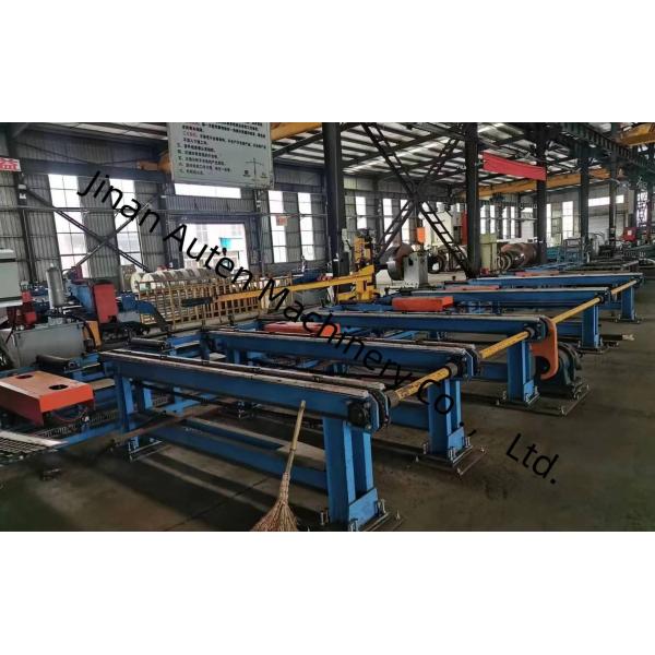
2000~12000mm Length Range Of Raw Material 3D Channel Beam Drilling
Machine 11KW Spindle Motor Power
Purpose of the production line:
This production line is primarily engineered to execute drilling,
marking, and milling operations on shaped steel (including H-beams
and channel steel)—core materials extensively utilized in steel
structure construction, bridge engineering, and heavy-duty
equipment manufacturing. It is specifically designed to carry out
these essential processing tasks with high precision, ensuring the
finished shaped steel complies with the stringent dimensional and
structural standards required for industrial applications.
Main Specifications:
| Parameter | Value |
| Workpiece size | Width range | 150~1250mm |
| Height Range | 100~600mm |
| Length range of raw material | 2000~12000mm |
| Length range of finished workpiece | 2000~12000mm |
| Drilling spindle | Number of drilling spindles | 3 |
| Spindle bore taper | BT40 |
| Spindle motor power | 11kW |
| Rotation speed | 200~3000 r/min |
| Drilling diameter range | φ5~φ30 |
| CNC axis | X-axis servo motor power | About 4.4kW |
| X-axis maximum speed | 40m/min |
| Servo motor power for drilling horizontal positioning axis | About 1.5kW |
| Max. speed of drilling horizontal positioning axis | 10m/min |
| Servo motor power of drilling horizontal feed axis | About 2kW |
| Max. speed of drilling horizontal positioning axis | 10m/min |
| Drilling vertical positioning axis servo motor power | About 3kW |
| Max. speed of drilling vertical positioning axis | 10m/min |
| Drilling vertical feed axis servo motor power | About 3kW |
| Max. speed of drilling vertical feed axis | 10m/min |
| Tool magazine | Quantity | 3 sets |
| Type | in-line type |
| Tool quantity | 4 x 3 |
| Hydraulic Marking unit | Qty. of characters | 36 |
| Character size | Φ10 |
1. Three-Dimensional Drilling Feeding Trolley
This component is composed of gears, servo motors, and
manipulators. The manipulator features excellent rigidity and
stability, and is capable of automatically lifting and lowering
according to profile specifications, as well as automatically
clamping workpieces. After the manipulator clamps a workpiece, it
is driven by the servo motor. Under the transmission of the
rack-and-pinion mechanism, the workpiece is fed in the
X-direction—effectively ensuring the longitudinal processing
accuracy of drilling operations.

2. Three-Dimensional Drilling Host
The drilling host is mainly composed of a base, a bed, a movable
slide, a spindle box, an upper pressing device, a side clamping
device, and a row-type tool magazine. The bed exhibits excellent
rigidity and stability, enabling it to withstand the load and
vibration generated during high-speed processing. This structural
performance effectively ensures the machining accuracy of the
machine tool throughout continuous operation.

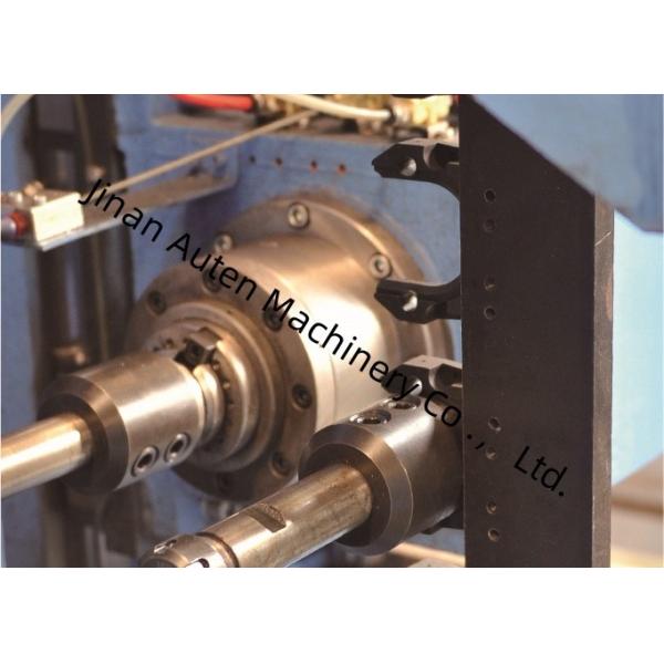
2. Three-Dimensional Drilling Host (Spindle Box Configuration)
The drilling host is equipped with 3 spindle boxes, namely the
fixed-side spindle box, movable-side spindle box, and upper-unit
spindle box, which are used for horizontal drilling and vertical
drilling operations respectively. Each spindle box can operate
independently or perform drilling operations simultaneously—this
configuration significantly enhances production efficiency. Each
spindle box is fitted with a set of BT40 high-speed mechanical
spindles; the corresponding row-type tool magazine can accommodate
up to 4 drill bits of different diameters (when no tool is mounted
on the spindle), enabling automatic machining of 4 distinct hole
diameters in a single workpiece clamping cycle.
The three spindle box units are mounted on the side of the bed.
Each spindle box unit is driven by two sets of servo motors to
realize the horizontal and vertical movement of the spindle
box—this movement is powered by a ball screw and guided by a
precision linear rolling guide, ensuring stable and accurate
positioning. During the drilling process, this equipment applies
pressing force to the workpiece in two directions. A
cylinder-driven pressing mechanism is arranged above the workpiece
to press the workpiece against the horizontal support rollers;
additionally, a cylinder-driven pressing mechanism is installed on
the side to apply lateral pressing force to the workpiece,
effectively securing the workpiece during machining.

In sample demonstration sessions, for instance, the machine tool
can effectively demonstrate its machining capabilities through
standard H-beam samples (with varying flange widths and web
thicknesses) and channel steel samples of different dimensions.
These displayed samples clearly illustrate the machine tool’s
ability to achieve accurate hole positioning, smooth tapped
threads, and distinct marking patterns—fully reflecting its high
precision and reliability in practical application scenarios.
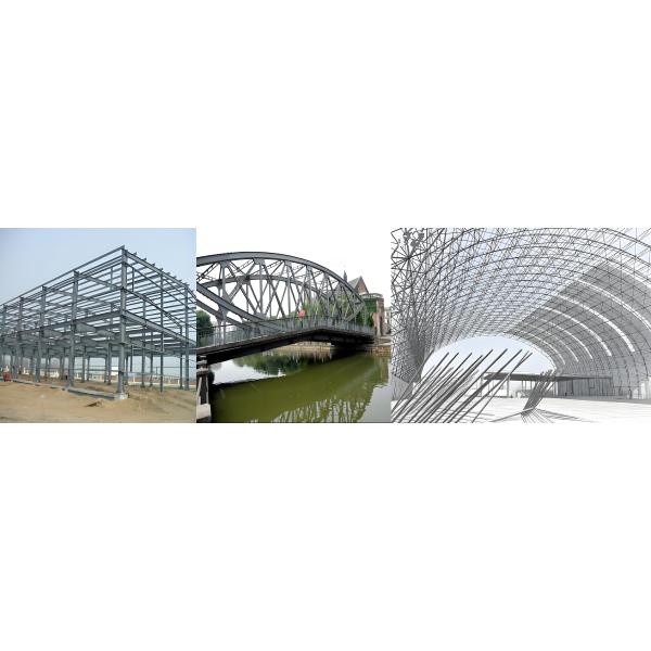
The High Speed CNC H Beam Drilling Machine is primarily utilized in
steel structure workshops and bridge construction projects. Within
steel structure workshops, it performs precision machining on
H-beams applied to frameworks and support structures, thereby
laying a solid foundation for the stable assembly of steel
structures. In bridge construction scenarios, it carries out
high-accuracy drilling operations on H-beams—this helps improve the
structural integrity of bridges, allowing them to bear long-term
loads. Its high operational efficiency provides reliable technical
support for these critical infrastructure sectors, ensuring the
smooth progression of project execution.


